Chapter 5: Installation
5.1. GENERAL DELIVERY NOTES
The machine is usually delivered on a wooden pallet with open wooden sides and top, attached with spring clips and covered in film to prevent it from being damaged during transportation.
Following receipt, check the machine condition; any damage should be communicated as soon as possible to the shipping agent by written notice.
Inspection
On delivery, always check the machine and equipment for any damage. Any damage must be notified in writing as soon as possible to the carrier or to the carrier’s insurance company.
5.2. UNLOADING AND POSITIONING THE MACHINE
If this is your first Corr-vac® Mark III, we strongly advise you to let a CV-TEK representative (or authorized agent) remove the crate, assemble the machine, attach a power supply and check the machine prior to putting it into service. Our representative will then train your personnel in safe operating procedures, troubleshooting and maintenance.

The machine should be moved to the desired position by using the wooden crate to which it is secured, so as to ensure better balancing and avoid damage during transportation.
Extreme care should be taken when using fork trucks. Check that the lifting capacity is sufficient before moving the machine. Make sure the forks are correctly positioned within the spaces provide in the wooden crate. Always make sure that the machine weight is correctly balanced with respect to the lifting point.
Removing the Crate
Crating will vary somewhat, depending upon the machine model and the options included. However, certain similarities will be found with all crating.
1. Remove the crate-top by first unsnapping the metal clips around the edges of the top face. Then carefully lift off the crate-top.
2. Remove the front and rear faces of the crate by unsnapping the metal clips around each face and then removing each face.
3. Before removing the end-faces, first remove the bolts which connect both faces to the wooden cross-bar in the crate. Then unsnap the remaining metal clips and remove both end-faces.
4. Remove the plastic film from around the machine.
5. Remove the wooden cross-bar from the machine.
6. Remove any parts or accessories which may have been taped to the exterior of the machine.
7. Open the doors at the back of the machine and remove all parts which are packed inside. Close and securely latch the doors.
8. Remove the bolts which fasten the machine to the base of the crate.
9. Un-wrap the machine ‘feet’ or optional castors packed inside the machine.

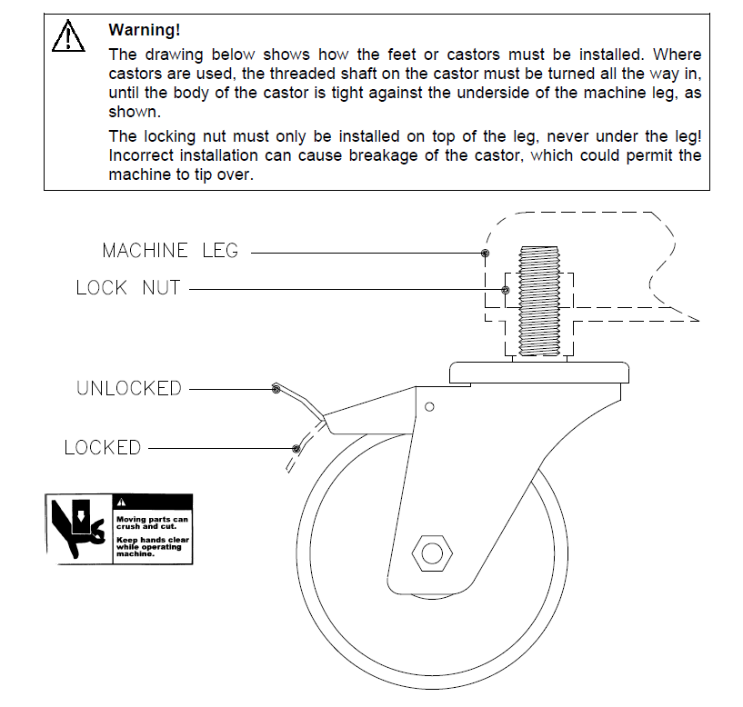
10. Lift the machine off the crate base and install the feet. The perimeter of the cabinet is reinforced so that lifting may be done at any point.

Head Position
If you are processing top-loaded packages, it is usually best for the operator if the machine head can be mounted at the approximate height of the operator’s shoulders.
For processing end-loaded bags, the most comfortable operating height is usually around 37 inches/940 mm from the bottom of the head to the floor.
The distance between the head and the packaging conveyor will be determined by the product and packaging geometry.

- Ensure that the wooden lifting cradle is securely in place on the head. It will help to
stabilize and protect the head while it is being moved.Also ensure that the jaw is securely wedged shut with the wooden shipping
wedge or fastened shut with tape, wire, etc. - If the head is mounted to the machine body with simple head spacers, they can
remain attached to the head throughout the moving procedure.If the machine is equipped with a HI-LO/joystick head mount, this head mount
must be removed before the head position is changed.
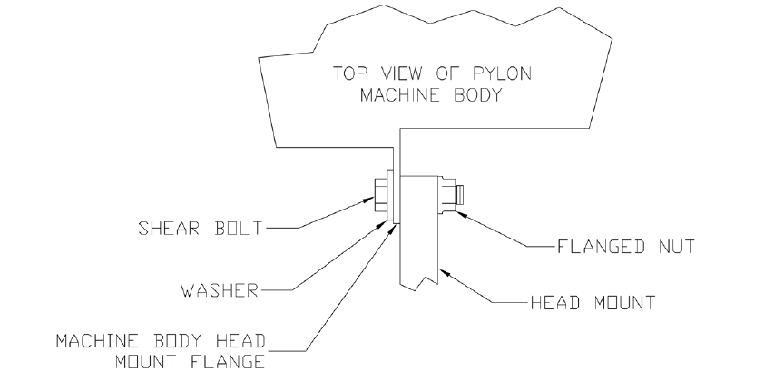
3. Before proceeding, study the “Head Mount” drawing below. Particularly note the position of the screws, washers, and nuts which secure the various head mounts to the machine body. It is essential that you reinstall these parts in the correct order. The shear bolts are specially made and should never be replaced with anything but a factory-supplied part.

4. If the machine is equipped with castors, securely lock all of them.
5. Slide the forks of a fork-lift all the way under the wooden lifting cradle, being careful not to strike the machine body. Gently raise the forks until they are just supporting the head.
6. If the machine has a HI-LO/joystick head mount, remove the two screws which secure the head mount to the back of the head. Then pull the head away from the machine, approximately 1 inch/25 mm. This should disengage the two mounting pins which extend rearward from the back of the head, into matching holes in the head mount.

7. Remove the shear bolts which secure the head mount to the machine body. Reposition the head mount at the desired height and reattach it to the body.
Move the head up/down to match the new height of the head mount. Slide the head toward the head mount until the two mounting pins engage. Then secure the head to the head mount with the two screws.
If the machine only has head spacers, detach the head spacers from the machine body. Then pull the head just far enough forward for the spacers to be clear of the body.
Move the head up/down to the desired height. Push the head back toward the machine body and properly re-secure the head spacers to the body.
Technical Assistance
For immediate technical assistance, please contact a CV-TEK machinery specialist at 847-741-3500.
5.3. SERVICE CONNECTIONS
Power Supply

1. Review the electrical drawings in this manual to determine what electrical supply will be needed. You will also find this information on a sticker inside the door of the machine’s electrical enclosure.
2. There is a cord compression fitting on the left end-wall (as viewed from the machine’s front) of the machine body. Bring your electrical cable through this fitting. Tighten the fitting so that it securely grips the cable, as well as creating a water-tight seal (note that there are two sizes of sealing grommets provided for different cable sizes).
3. Connect the power wiring into the terminals at the top of the main electrical disconnect switch.

4. Before energizing the machine’s main electrical disconnect switch, take a voltmeter and carefully check the power at the terminals on top of the switch.
- Check power between any terminal and the machine body to verify that the ground (earth) is working
- Check power between all terminals to verify that all phases have the correct voltage

5. Before energizing the machine, first open the machine jaw. Then energize the main disconnect switch.
- Check that the EMERGENCY STOP BUTTON is illuminated (if it is not, pull it out to its normal operating position). This indicates that the machine’s control system is receiving power
- If the machine contains a vacuum pump operating on three-phase power, the motor rotation must now be checked

Pump Rotation
- Remove one of the plastic vacuum tubes at a vacuum probe.
- Briefly close the machine jaw to start the vacuum pump. If you feel pressure at the
end of the plastic tube (instead of vacuum), immediately press the EMERGENCY
STOP BUTTON to stop the pump, as it is running backwards.
For all models, the pump motor rotation can be reversed at the motor
starter/overload protector inside the machine body.
- Turn off the power at the main electrical disconnect switch.
- Locate the three wires coming out of terminals at the bottom of the motor
starter/overload protector unit. Reverse the location of any two of these wires to
reverse the motor direction. - Turn on the power to the machine and retest to verify that the pump is running
correctly.
Compressed Air


1. The filter/regulator/lubricator (FRL) unit is mounted on the left end-wall (as viewed from the machine’s front) of the machine body. Check the MACHINE SPECIFICATIONS section of this manual for compressed air requirements.

2. Compressed air should be supplied to the inlet port (left-hand end) in the FRL.
3. Set the FRL pressure regulator as follows:
- All sealers except 61 ½ inch / 1560 mm: 100 psi / 6.8 bar
- 61 ½ inch / 1560 mm sealers: 110 psi / 7.5 bar
Gas Supply

All gas connections are located on the right end wall (as viewed from the machine’s front) of the machine body. Check the MACHINE SPECIFICATIONS section of this manual for compressed gas requirements.

